 |
|
|
|
| |
|
|
|
|
User Manual for QCad

|
|
|
|
| |
|
|
|
| |
|
|
15.1 Creating Your Own Fonts
|
| |
|
|
| | QCad allows you to change existing fonts or add new ones. You can load an existing font like any other file. The fonts can be located in three different paths: | | |
|
| |
|
|
| | /usr/share/qcad/fonts
/usr/local/qcad/fonts
~/.qcad/fonts | | |
|
| |
|
|
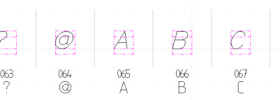
| | The extension for fonts is CXF which stands for CAM Expert font. After loading a font you can add or change characters using the normal functions of QCad. Every character must be located in the given range (gray border). However, there's no limit in the y direction but you should strictly abide the limits in x axis. | | |
|
| |
|
|
| |
 |
|
Fig. 21: The font editing mode
|
| | |
|
| |
|
|
| | The border is located on a layer called "Border" while the characters of the font are located on layer "Letters". Objects which are not in the valid range of a character will be lost while you save the font. It may be a good idea to save the font as a DXF file as well to ensure that nothing gets lost by accident. DXF font files can get reloaded and then saved as fonts again. | | |
|
| |
|
|
| | If you've created a nice font and want to give it away for free, please send it to me by e-mail. I'll include it in the next release of QCad. | | |
|
| |
|
|
15.2 Creating Your Own Patterns
|
| |
|
|
| | You can create your own additional patterns for QCad. Just make a square with the pattern and save it to the pattern directory of QCad. The square must have a size of 100x100. QCad detects all DXF files from that directory automatically. A pattern can only contain lines, no other objects. Please note, that patterns should not contain many objects. The more objects they contain, the slower gets the hatching function of QCad. | | |
|
| |
|
|
15.3 Creating Object Libraries
|
| |
|
|
| | QCad supports the usage of object libraries. See also chapter Object Libraries for a guide how to insert objects into your drawing. | | |
|
| |
|
|
| | Before you start creating your own object library, you should read this part of the manual to be sure that you profit from the whole functionality that QCad offers. | | |
|
| |
|
|
| | It's also very important that you don't do a work which another one has already done. To avoid this, there's a list with existing object libraries and such which are under construction. You'll find this list on the QCad home page. | | |
|
| |
|
|
15.3.1 Object Hierarchy
|
| |
|
|
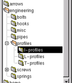
| | QCad can handle any desired hierarchy for object libraries. However, I recommend to use not more than three levels. The top folders in the library hierarchy are for example: "engineering", "home", "architecture", "borders", "arrows" and so on. The following figure shows an example of an object library hierarchy. | | |
|
| |
|
|
| |
 |
|
Fig. 22: Example for an object library hierarchy.
|
| | |
|
| |
|
|
15.3.2 Directory Structure
|
| |
|
|
| | You can place your libraries in the following directories: | | |
|
| |
Library Paths
|
|
| | /usr/share/qcad/libraries
/usr/local/qcad/libraries
~/.qcad/libraries | | |
|
| |
|
|
| | QCad will search all these directories and their sub directories for files in knows formats. You can specify two more paths in the options dialog and several more in the configuration file. | | |
|
| |
|
|
| | Please note that the Object Browser joins the contents of all directories. This means that if there's a sub directory called "engineering" in both the "~/.qcad/libraries" and the "/usr/local/qcad/libraries" directory, it will appear as one folder in the object browser. The files of both paths are included in the preview. This way you can add files to any section by saving them to the right path in your home directory. | | |
|
| |
|
|
15.3.3 Creating Objects
|
| |
|
|
Choosing The Right Scale
|
| |
|
|
| | Think well about the scale you use for your library. It should be the most common scale or a scale in which the most important dimension of the part has a length of 1. This way the user can choose the length of this dimension in the "factor" box. | | |
|
| |
|
|
| | For example if you design a library of metric screws, it's probably the best if you construct all screws with a diameter of 1mm. The user who inserts an object can simply type the diameter in the "factor" box. | | |
|
| |
|
|
The Zero Point
|
| |
|
|
| | The absolute zero point of the drawing used for an object is the reference point for inserting the object into the drawing. | | |
|
| |
|
|
Using The Right Layers
|
| |
|
|
| | To stay clear, it's important that all object library designers use the same layer model. If a user inserts an object into his drawing, all layers required for the object get created automatically to put the object on these layers. To avoid the appearance of new layers for every inserted object, you should use mainly these layers for your objects: | | |
|
| |
Common Layers
|
|
| | Layername | Usage | OBJECT | The actual object | AUXILIARY | Center lines and other help lines | DIM | Dimensions | TEXT | Texts | HATCH | Hatches |
| | |
|
| |
|
|
Defining Stretch Areas
|
| |
|
|
| | Many objects can exist in different lengths, heights or diameters. To avoid that every possible variation of an object must be constructed and saved in an object library, QCad offers the possibility to define stretchy parts. It's probably the best to illustrate this feature with the following example. | | |
|
| |
|
|
Example screw
|
| |
|
|
| | Let's take a screw which exists in various lengths. You need to have this screw only once in your library. The following steps guide you through the process of creating such an object. | | |
|
| |
|
|
1st Step
|
| |
Reference Length
|
|
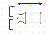
| | Create the screw with a reasonable length. In the example a reference length (r) of 2mm was chosen. This reference length doesn't matter, you'll see later why. Please put the elements on the right layer like described above. | | |
|
| |
|
|
| |
 |
|
Fig. 23: Example screw with a reference length of 2mm.
|
| | |
|
| |
|
|
2nd Step
|
| |
Stretching Position
|
|
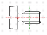
| | Now we need to define the position where the screw must be stretched (we don't want to stretch it's head but only it's thread). This is done with one line on a certain layer. This line "divides" the screw at the stretch position. | | |
|
| |
|
|
| |
 |
|
Fig. 24: The green line defines the stretching point.
|
| | |
|
| |
|
|
| | This special line is just for internal use and doesn't appear when the user inserts the object. To tell the program that this line defines the stretching position it must be on a certain layer. The color and style don't matter but I recommend to make this line in a dark green with a two dotted line style. | | |
|
| |
Layer Of Stretching Line
|
|
| | The layer name of the green line used in the example is: "_stretch_lr_2". The beginning of the layer name has always to be "_stretch_". The next letter "l" says that the user gets asked for a length for this part. The "r" stands for "right". This is needed for the program to know to which side it should enlarge or shorten the part. Then follows an underscore "_" and at last the used reference length. The reference length is needed by the program to calculate the stretch amount. If the user types "10" for the screw length, it must be stretched by 8 (=10-2) because it already has a length of 2. The reference length in the layer name can as well be a float value (e.g. "2.5"). | | |
|
| |
|
|
Possible Layer Names For Stretch Lines
|
| |
|
|
| | The following list shows all valid layer names for stretching lines. As reference length is always taken "10" but this can vary of course. | | |
|
| |
|
|
| | Layer Name | Function | _stretch_ll_10 | Stretch length to the left. | _stretch_lr_10 | Stretch length to the right. | _stretch_lc_10 | Stretch length to the left and to the right (centered). | _stretch_hu_10 | Stretch height upwards. | _stretch_hd_10 | Stretch height downwards. | _stretch_hc_10 | Stretch height upwards and downwards (centered). |
| | |
|
| |
|
|
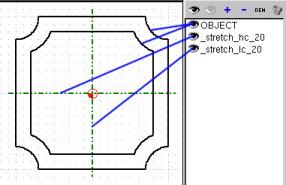
| | The following figure shows an example for a simple object with a height and a length. | | |
|
| |
|
|
| |
 |
|
Fig. 25: Example object with variable height and length.
|
| | |
|
| |
|
|
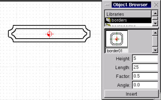
| | For such an object, the user can type the height, length, factor and the angle. If a border with a length of 25mm, a height of 5mm and a border width of 1mm is required, the user must type the values shown in the figure below. | | |
|
| |
|
|
| |
 |
|
Fig. 26: Example usage of the above object.
|
| | |
|
| |
|
|
[ 1-2-3-4-5-6-7-8-9-10-11-12-13-14-15-16-17-18 ]
Copyright © by Andrew Mustun 1999-2001. All rights reserved.
This Manual was created with ManStyle.
|


