|
|
|
|
| |
|
|
|
|
User Manual for QCad

|
|
|
|
| |
|
|
|
| |
|
|
9.1 Creating Points
|
| |

|
|
| | Click this button from the toolbar to show the "Points" toolbar. | | |
|
| |
|
|
9.1.1 Creating Single Points
|
| |

|
|
| | Use this tool to create points in the drawing. | | |
|
| |
|
|
9.2 Creating Lines
|
| |

|
|
| | Click this button from the toolbar to show the "Lines" toolbar. | | |
|
| |
|
|
9.2.1 Creating Lines
|
| |

|
|
| | Create lines by clicking the start point and the endpoint. | | |
|
| |
|
|
9.2.2 Creating Lines With Given Angles
|
| |

|
|
| | Create lines by typing the angle and clicking the position. The line gets constructed on to the borders of the screen. This is thought for later trimming. | | |
|
| |
|
|
9.2.3 Creating Horizontal Lines
|
| |

|
|
| | This tool draws horizontal lines on to the borders of the screen. Trim the lines to the desired length afterwards. | | |
|
| |
|
|
9.2.4 Creating Vertical Lines
|
| |

|
|
| | The same as horizontal lines just vertical. | | |
|
| |
|
|
9.2.5 Creating Rectangles
|
| |

|
|
| | Create rectangles by clicking two diagonal edges. | | |
|
| |
|
|
9.2.6 Creating Parallels
|
| |

|
|
| | Create lines parallel to existing lines. You can specify the distance in the box appearing at the top left of the window.
This tool works for arcs and circles as well. | | |
|
| |
|
|
9.2.7 Creating Bisectors
|
| |

|
|
| | Create lines in the half angle between two existing lines. You can specify the length in the box appearing at the top left of the window.
The bisector appears between the two lines and at the same side of the lines where the mouse cursor was located while clicking the objects. | | |
|
| |
|
|
9.2.8 Creating Tangents From Points To Circles
|
| |

|
|
| | Choose the point and then the circle or arc. The tangent gets drawn to the circle. As there are two possibilities, the one is drawn, which is next to the mouse cursor while clicking the circle. | | |
|
| |
|
|
9.2.9 Creating Tangents From Circles To Circles
|
| |

|
|
| | Choose the circles. The tangent gets drawn between the circles. As there are four possibilities, the one is drawn, which is next to the mouse cursor while clicking the second circle. | | |
|
| |
|
|
9.2.10 Creating Orthogonal Lines
|
| |

|
|
| | Choose the base element and set the position. A line gets created perpendicular to the base element. | | |
|
| |
|
|
9.2.11 Creating Lines With Relative Angles
|
| |

|
|
| | Choose the base element, type an angle and set the position.
A line gets created with the given relative angle to the base element. | | |
|
| |
|
|
9.3 Creating Arcs
|
| |

|
|
| | Click this button from the toolbar to show the "Lines" toolbar. | | |
|
| |
|
|
9.3.1 Creating Arcs (C,P,A)
|
| |

|
|
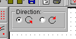
| | This can be used to draw arcs with a given center, circle line and the start / end angles. Click the center, a point on the circle line and then a point on the imaginary line from the center to the start point of the arc and a point on the imaginary line from the center to the end point of the arc. During one of these operations you can choose the direction of the arc in the box appearing at the top left of the window:
 | | |
|
| |
|
|
9.3.2 Creating Arcs (SP,P,EP)
|
| |

|
|
| | With this tool you can create arcs with three points given: The start point, a point somewhere between on the arc and the endpoint. Click the start point first, then a point between and at last the endpoint. | | |
|
| |
|
|
9.3.3 Creating Parallel Arcs
|
| |

|
|
| | Create arcs parallel to existing ones. You can type the distance of the arc in the box appearing at the top left of the window.
This tool works for lines as well. | | |
|
| |
|
|
9.4 Creating Circles
|
| |

|
|
| | Click this button from the toolbar to show the "Circles" toolbar. | | |
|
| |
|
|
9.4.1 Creating Circles
|
| |

|
|
| | Create circles with a given center and a given radius. Enter a radius in the radius box at the top left and click the center(s) of the circle(s). | | |
|
| |

|
|
| | Create circles with a given center and a point on the circle line. Click the center and then the point on the circle line. | | |
|
| |

|
|
| | Create circles with three points on the circle line. Click all three points on the circle line to create a circle. | | |
|
| |
|
|
9.5 Creating Texts
|
| |

|
|
| | Click this button from the toolbar to create texts. | | |
|
| |
|
|
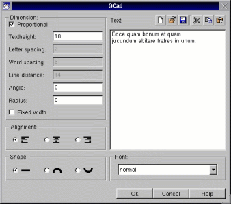
| | The text dialog box appears:
 | | |
|
| |
|
|
| | Tick the "Proportional" check box to automatically adjust the values "Letter spacing", "Word spacing" and "Line distance" to the "Textheight". If you don't tick "Proportional" you can adjust these values individually. | | |
|
| |
|
|
| | You can create texts with a fixed letter width by ticking the check box "Fixed width". This can be useful for inserting ASCII files which are formatted with spaces (lists, tables). For such purposes it's recommended to use the font "courier". | | |
|
| |
|
|
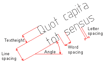
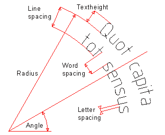
| | Type the values for "Textheight", "Letter spacing", "Word spacing", "Line distance", "Angle" and "Radius". The following sketches give you an idea about the meaning of these parameters: | | |
|
| |
|
|
| |
 |
|
Fig. 4: Parameters for straight texts.
|
| | |
|
| |
|
|
| |
 |
|
Fig. 5: Parameters for rounded texts.
|
| | |
|
| |
|
|
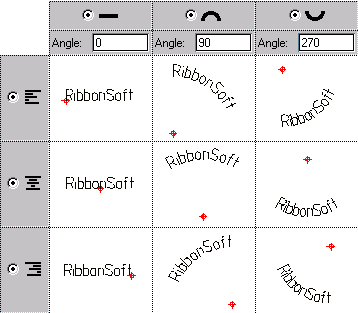
| | Choose the alignment and the text shape by clicking on the icons to activate the radio buttons. The following table gives you an overview of the possible combinations: | | |
|
| |
|
|
| |
 |
|
Fig. 6: The different text shapes.
|
| | |
|
| |
|
|
| | Choose a font from the "Font" combo box. Possible fonts are: | | |
|
| |
|
|
| | | ISO normal |  | | ISO cursive |  | | Courier | 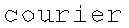 |
| | |
|
| |
|
|
| | Type the text in the text area or load an existing text field into the area. You can also paste a text which you have copied in another application. | | |
|
| |
|
|
| | There are some other functions available for the text area in the text dialog: | | |
|
| |
|
|
| |  Click to erase the text area. Click to erase the text area.
 Click to open an existing file into the text area. Click to open an existing file into the text area.
 Click to save the current text into a file. Click to save the current text into a file.
 Click to cut the selected text to the clipboard. Click to cut the selected text to the clipboard.
 Click to copy the selected text to the clipboard. Click to copy the selected text to the clipboard.
 Click to paste the text on the clipboard to the text area. Click to paste the text on the clipboard to the text area.
| | |
|
| |
|
|
Creating Your Own Fonts
|
| |
|
|
| | QCad allows you to create your own fonts or change the existing fonts. You may for example be interested to add letters you're missing to a font. | | |
|
| |
|
|
9.6 Creating Dimensions
|
| |
|
|
9.6.1 The dimension options panel
|
| |
|
|
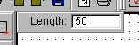
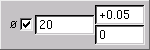
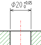
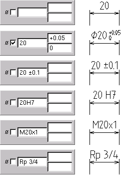
| | Most dimensioning tools show a panel at the top left of the graphic window. This panel allows you to configure the label of the current dimension. | | |
|
| |
|
|
| |
 |
|
Fig. 7: The dimension panel is used for adjusting the dimension's label.
|
| | |
|
| |
|
|
| |
 |
|
Fig. 8: A dimension created with the settings shown above.
|
| | |
|
| |
|
|
| |
 |
|
Fig. 9: Some more examples for dimensioning labels.
|
| | |
|
| |

|
|
| | Click this button from the toolbar to show the "Dimensions" toolbar. | | |
|
| |
|
|
9.6.2 Creating Aligning Dimensions
|
| |

|
|
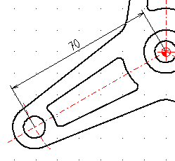
| | This tool will create a dimension which is parallel to an imaginary line between two given points. The extension lines are drawn to the two points. | | |
|
| |
|
|
| |
 |
|
Fig. 10: For this example, the two center points of the circles were chosen as references.
|
| | |
|
| |
|
|
| | After setting the reference points, you must also set the location of the dimension line. | | |
|
| |
|
|
9.6.3 Creating Horizontal / Vertical Dimensions
|
| |
 
|
|
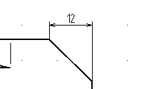
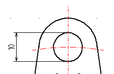
| | These often used dimensioning tools allows you to create horizontal / vertical dimensions. The two reference points don't have to be on the same horizontal / vertical line. | | |
|
| |
|
|
| |
 |
|
Fig. 11: The reference points for this dimension are the endpoints of the bevel.
|
| | |
|
| |
|
|
9.6.4 Creating Angle Dimensions
|
| |

|
|
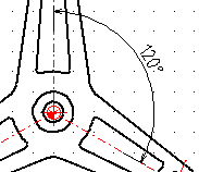
| | With this tool, it's possible to create angle dimensions between two lines. If you need to dimension an angle but don't have two lines, I recommend to construct two auxiliary lines first. You can delete these lines after doing the dimensioning, if you like. | | |
|
| |
|
|
| | First you have to click the two lines which define the angle (counter-clockwise). Then you can set the dimensioning line location and afterwards the endpoints of the extension lines. | | |
|
| |
|
|
| |
 |
|
Fig. 12: A typical angle dimension.
|
| | |
|
| |
|
|
9.6.5 Creating Diameter Dimensions
|
| |

|
|
| | For dimensioning diameters of circles, you can use this tool. Simply click the circle, set the angle and the location of the dimension line. | | |
|
| |
|
|
| |
 |
|
Fig. 13: Diameter dimension.
|
| | |
|
| |
|
|
9.6.6 Creating Radius Dimensions
|
| |

|
|
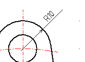
| | Click the angle or circle and set the location of the dimension endpoint respectively the position of the measuring text. | | |
|
| |
|
|
| |
 |
|
Fig. 14: Radius dimension.
|
| | |
|
| |
|
|
9.6.7 Creating Arrows
|
| |

|
|
| | This tool allows you to draw arrows by defining the start and the end point. The second point is the point where the arrow appears. The arrow gets drawn without any text besides. | | |
|
| |
|
|
9.7 Creating Hatches
|
| |

|
|
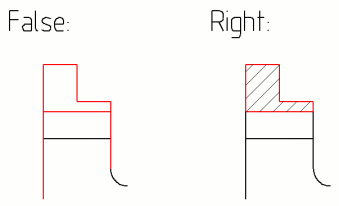
| | After choosing this function you must select the elements of one or more closed contours. The elements should be connected properly. Otherwise the result is undefined. If you select two overlapping contours, however, every other area gets hatched. QCad currently can't hatch contours given by not connected but intersected bounding objects. Please cut these objects at the edges and select only the closed contour then, like shown in the figure below. | | |
|
| |
|
|
|
| |
|
|
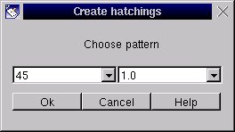
| | If you've chosen the contours, click the arrow button at the bottom of the selecting toolbar. The hatching dialog box appears: | | |
|
| |
|
|
|
| |
|
|
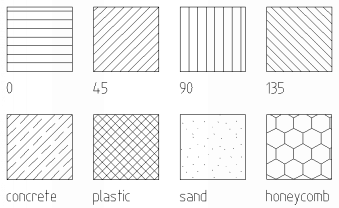
| | In the left combobox, you can choose a pattern and in the right one the factor for the pattern. Currently there are these patterns available as defaults: | | |
|
| |
|
|
|
| |
|
|
9.7.1 Creating Your Own Patterns
|
| |
|
|
| | You can also create your own additional patterns for QCad. Please refer to chapter Additional Features for more information. | | |
|
| |
|
|
[ 1-2-3-4-5-6-7-8-9-10-11-12-13-14-15-16-17-18 ]
Copyright © by Andrew Mustun 1999-2001. All rights reserved.
This Manual was created with ManStyle.
|